3D-Printed Metal Cold Plate
- Role
- Independent project
- Dates
- Nov 2026 – present
- Status
- In progress
- Tools
- ANSYS Fluent, SolidWorks, Python
- Project
- P02
Abstract
Three cold plates sit in the same loop: machined channels, printed channels, and a printed gyroid lattice. Running all three at 0.25–2 L/min and 50–150 W separates the effect of geometry from the effect of manufacturing, because the printed-channel plate shares its shape with the machined one and its process with the lattice.
Laminar-flow hand calculations put the machined plate at 0.079–0.094 K/W, the benchmark the CFD has to reproduce before any metal is printed. The same calculations found a flaw in the rig: fitting losses of about 2 kPa are roughly 20× the plate's own core pressure drop, so the pressure taps belong in the manifolds rather than across the fittings.
The question matters well beyond spacecraft — the same geometry argument drives data-centre liquid cooling and EV battery plates.
Take it apart
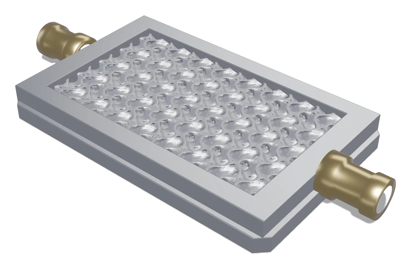
The gyroid plate of the three: a printed lattice core sealed between a base plate and a manifold frame. Scroll to take it apart.
- The assemblyWhat it is, put together.
- Taken apartKeep scrolling. Every part comes off along its own axis, the way it would on the bench.
- What each part doesClick any label, or any part, to see its name and why it is there.
Files
4 folders · 4 files · 1 open in the browser, nothing downloads. 3 files are not uploaded yet.
Analysis
P02 / 02_Analysis| Type | File | Rev | Date | Status | Open |
|---|---|---|---|---|---|
| P02_Gate1_Hand_Calcs.pdfWorked hand calculations | — | — | Planned |
CAD
P02 / 03_CAD| Type | File | Rev | Date | Status | Open |
|---|---|---|---|---|---|
| MD | Every part in the plate, its spec and what it is for | A | Nov 2026 | Current |
Simulation
P02 / 04_Simulation| Type | File | Rev | Date | Status | Open |
|---|---|---|---|---|---|
| MD | P02_Fluent_CFD.mdThree geometries | — | — | Planned |
Procurement
P02 / 11_Procurement| Type | File | Rev | Date | Status | Open |
|---|---|---|---|---|---|
| XLSX | P02_Print_Quotes.xlsxMetal print vendors | — | — | Planned |
| Item | Part | Spec | What it is for |
|---|---|---|---|
| 01 | Gyroid lattice core | Printed aluminium | The printed core under test. Its surface area is the thing the comparison is built to measure, against machined channels and against printed channels of the same shape. |
| 02 | Manifold frame | Aluminium | Encloses the flow path and carries the ports. The pressure taps belong in the manifolds rather than across the fittings, because fitting losses run roughly 20× the plate's own core pressure drop. |
| 03 | Base plate | Aluminium | Closes the bottom of the flow path and carries the mounting holes. The machined version of this plate is the 0.079–0.094 K/W benchmark the CFD has to reproduce. |
| 04 | Inlet fitting | — | Feeds the plate from the loop at 0.25–2 L/min. |
| 05 | Outlet fitting | — | Returns the coolant. The temperature rise between the two ports is how much of the 50–150 W the plate actually carried away. |
Item numbers match the numbered callouts on the exploded view. A dash means the part is on the model but carries no callout.
Not uploaded yet.