Self-Pointing Satellite Testbed
- Role
- Independent project
- Dates
- Sep 2026 – present
- Status
- In progress
- Tools
- MATLAB, Simulink, SolidWorks, ANSYS
- Project
- P01
Abstract
A 0.8 kg, 3U-scale satellite model hangs from a 2 m nylon line and turns itself with a brass reaction wheel, the way a spacecraft points without propellant. The maneuver is a 90° turn in 20 s followed by a ±2° hold for 60 s, judged by a camera reading an ArUco marker on the underside that never feeds the controller.
Hand calculations size the wheel to 4.2× the momentum the turn needs and the frame to a 374 Hz bolted first mode against a 150 Hz requirement, 2.5× the figure asked for. An error budget puts the pointing error of the first design at 2.7°; feedforward for the line's twist and a lower-drift gyro bring it to 1.1°.
Thirteen tests are laid out, each with its target written down before it runs, so the comparison between model and hardware is the result rather than an afterthought.
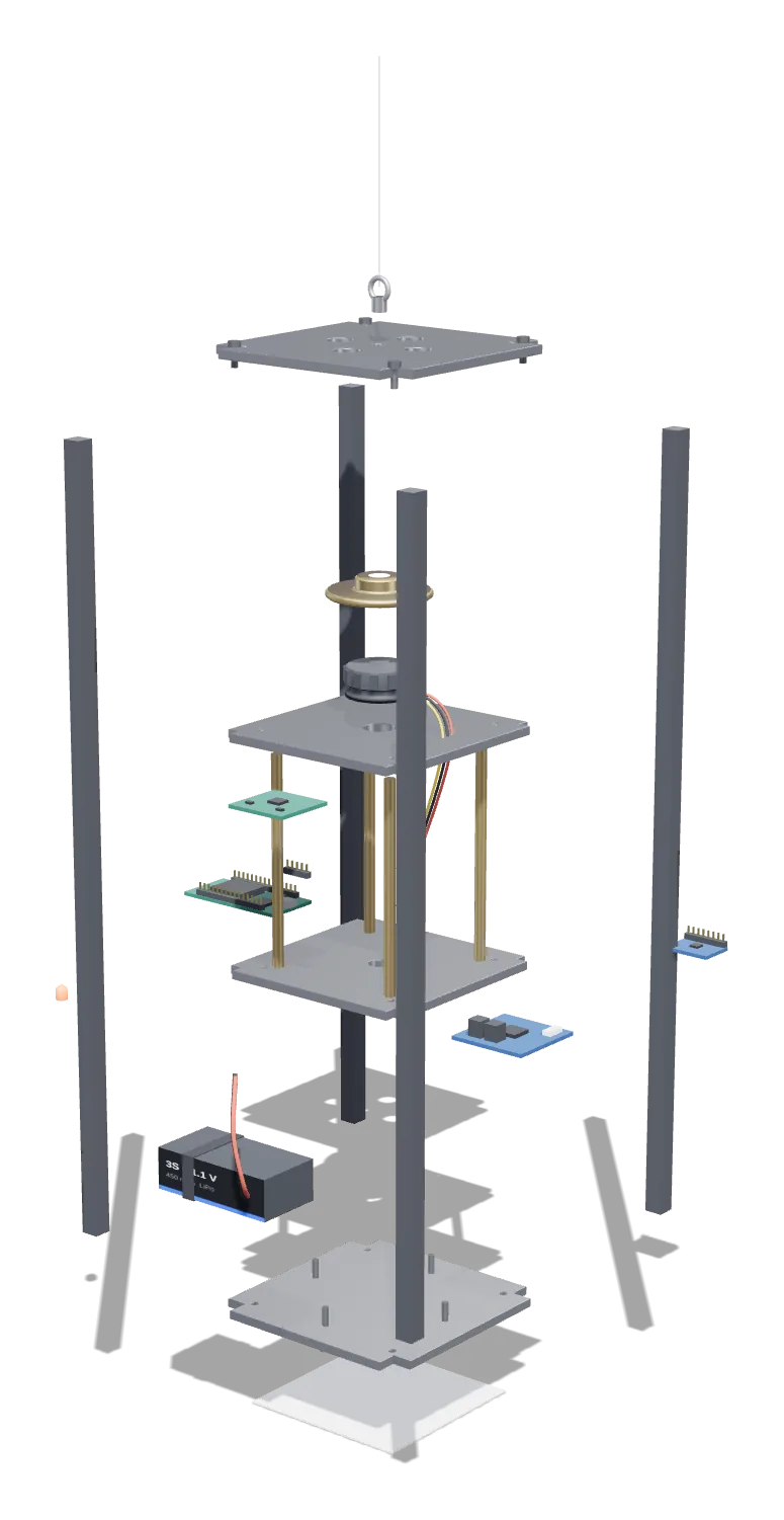
Take it apart
A 0.8 kg satellite model that hangs from a nylon line and turns itself with a brass reaction wheel. Scroll to take it apart.
- The assemblyWhat it is, put together.
- Taken apartKeep scrolling. Every part comes off along its own axis, the way it would on the bench.
- What each part doesClick any label, or any part, to see its name and why it is there.
Files
9 folders · 11 files · 9 open in the browser, nothing downloads. 2 files are not uploaded yet.
Admin
P01 / 00_Admin| Type | File | Rev | Date | Status | Open |
|---|---|---|---|---|---|
| XLSX | Risks scored by likelihood × consequence | C | Nov 2026 | Current | |
| MD | Dated design decisions | B | Nov 2026 | Current |
Requirements
P01 / 01_Requirements| Type | File | Rev | Date | Status | Open |
|---|---|---|---|---|---|
| XLSX | Requirements and verification matrix | B | Nov 2026 | Current |
Analysis
P01 / 02_Analysis| Type | File | Rev | Date | Status | Open |
|---|---|---|---|---|---|
| P01_Gate1_Hand_Calcs.pdfWorked hand calculations | — | — | Planned | ||
| XLSX | Functions × options | A | Nov 2026 | Current |
CAD
P01 / 03_CAD| Type | File | Rev | Date | Status | Open |
|---|---|---|---|---|---|
| DWG | Brass flywheel, Rev A | A | Nov 2026 | Current | |
| MD | Every part in the assembly, its spec and what it is for | A | Nov 2026 | Current |
Simulation
P01 / 04_Simulation| Type | File | Rev | Date | Status | Open |
|---|---|---|---|---|---|
| PNG | 90° slew and 60 s hold from the Gate 1 model | B | Nov 2026 | Current |
Fabrication
P01 / 06_FabricationBuild photos go here once fabrication starts.
Test
P01 / 07_Test| Type | File | Rev | Date | Status | Open |
|---|---|---|---|---|---|
| XLSX | T-01 to T-13, target before the run | A | Nov 2026 | Current |
Report
P01 / 09_Report| Type | File | Rev | Date | Status | Open |
|---|---|---|---|---|---|
| P01_Final_Report.pdfDue Dec 2026 | — | Dec 2026 | Planned |
Procurement
P01 / 11_Procurement| Type | File | Rev | Date | Status | Open |
|---|---|---|---|---|---|
| XLSX | Planned vs ordered vs received | C | Nov 2026 | Current |
| Row | A | B | C | D | E | F | G |
|---|---|---|---|---|---|---|---|
| 1 | ID | Requirement | Method | Calc # | Test ID | Pass criterion | Status |
| 2 | R-01 | Rotation about yaw only; swing and tilt kept small | T, A | #6, #7 | T-09 | Swing amplitude and tilt below the value set by calc #6/#7 | Not started |
| 3 | R-02 | 90° slew in ≤ 20 s, settling within ±2° | T | #1, #11 | T-09 | Camera: settle inside ±2° by t ≤ 20 s, repeated runs | Not started |
| 4 | R-03 | Hold ±2° for 60 s after settling | T | #10, #11 | T-10 | Camera: |error| ≤ 2° for 60 s | Not started |
| 5 | R-04 | Truth sensor independent of the control sensor | I, T | — | T-01 | Camera never in loop; camera error within budget on protractor stage | Not started |
| 6 | R-05 | Wheel capacity ≥ 2× slew momentum at the operating speed limit | A, T | #2, #12 | T-13 | Margin ≥ 2.0 (currently 4.2× at 1,000 rpm) | Not started |
| 7 | R-06 | No wiring across the suspension | I | — | — | Visual inspection | Not started |
| 8 | R-07 | First structural mode ≥ 150 Hz | A, T | #8 | T-07 | FEA (2 codes) and tap test ≥ 150 Hz; FEA within 15% of test | Not started |
| 9 | R-08 | Battery supports a full test sequence on one charge | A, T | #13 | T-12 | Full sequence completed above low-voltage cutoff | Not started |
| 10 | R-09* | Gyro and camera logs share a time base to ≤ 50 ms | D | — | T-01 | Sync event (MCU-triggered LED seen by camera) aligns logs | Not started |
| 11 | R-10* | LiPo handled safely: balance charger, fire-safe bag, low-voltage cutoff in firmware | I | #13 | — | Checklist signed before first powered test | Not started |
| 12 | R-11* | Hardware cost ≤ $270 | A | — | — | BOM actual total ≤ budget | Not started |
| 13 | * Suggested additions — keep, change or delete at Gate 1. |
| Row | A | B | C | D | E | F | G |
|---|---|---|---|---|---|---|---|
| 1 | Item | Description | Part / spec | Qty | Unit low ($) | Unit high ($) | Status |
| 2 | 1 | Gimbal motor + FOC driver board | 2204-class gimbal BLDC; driver per TS-2 | 1 | 25 | 45 | To quote |
| 3 | 2 | Microcontroller + magnetic encoder | ESP32 dev board; encoder per TS-2 | 1 | 15 | 30 | To quote |
| 4 | 3 | IMU breakout | Per TS-3 (published noise density) | 1 | 15 | 25 | To quote |
| 5 | 4 | 3S LiPo (~450 mAh) + balance charger + fire-safe bag | Per calc #13 | 1 | 25 | 45 | To quote |
| 6 | 5 | C360 brass rod, 1-1/2 in | Flywheel + spare for V2 | 1 | 25 | 35 | To quote |
| 7 | 6 | 6061-T6 sheet 1/8 in, 5/16 in square bar, M3 hardware | Plates, rails, fasteners | 1 | 25 | 40 | To quote |
| 8 | 7 | Nylon line, stainless eyelet, marker print | Per TS-1 | 1 | 10 | 20 | To quote |
| 9 | 8 | Camera | Existing phone or webcam | 1 | 0 | 30 | To quote |
| 10 | 9 | Suggested: spare IMU + spare encoder | Covers RK-14 | 1 | To quote | ||
| 11 | 10 | Suggested: Al calibration block for bifilar check (T-02) | Machinable from 6061 bar | 1 | To quote | ||
| 12 | 11 | Suggested: LED + resistor for camera time sync (R-09) | 1 | To quote | |||
| 13 | Subtotal | 140 | 270 | ||||
| 14 | Contingency 15% | 21 | 40.5 | ||||
| 15 | Total with contingency | 161 | 310.5 | ||||
| 16 | Budget (program overview) | 140 | 270 |
| Row | A | B | C | D | E | F | G | H |
|---|---|---|---|---|---|---|---|---|
| 1 | ID | Risk (if… then…) | Category | L | C | Score | Level | Mitigation |
| 2 | RK-01 | If residual gyro bias is a few hundredths of °/s, then integrated drift over 80 s uses most of the ±2° budget | Technical | 4 | 4 | 16 | High | Pick IMU on bias stability (TS-3); warm-up + bias cal before every run; Allan variance (T-05); quantify drift vs camera |
| 3 | RK-02 | If the line's restoring torque isn't compensated, then PD leaves ~0.7° steady-state error and the wheel keeps spinning up during holds | Technical | 5 | 3 | 15 | High | k_s·θ_ref feedforward or integral term; return to 0° between runs; model it in Simulink |
| 4 | RK-03 | If the frame's first torsion mode is lower than the 132 Hz estimate, then R-07 fails | Technical | 3 | 3 | 9 | Medium | Re-derive calc #8 (which inertia twists, bays in series); 2 FEA codes; tap test; shear-panel fallback |
| 5 | RK-04 | If nylon creeps or untwists over hours, then the neutral angle and k_s drift between runs | Technical | 4 | 3 | 12 | Medium | Pre-load the line 24–48 h; record neutral angle each session; trade steel wire (TS-1) |
| 6 | RK-05 | If cogging/stiction near 0 rpm causes limit cycles, then pointing chatters | Technical | 3 | 3 | 9 | Medium | FOC; run the wheel at a bias speed so it never crosses zero; spin-down friction model |
| 7 | RK-06 | If the CAD inertia and the real inertia disagree, then gains and slew times are off | Technical | 4 | 2 | 8 | Medium | Bifilar (T-02/T-03) before any tuning; update model with as-built masses |
| 8 | RK-07 | If swing couples into yaw, then camera and gyro readings are corrupted | Technical | 3 | 3 | 9 | Medium | Damp swing before runs; CG trim; separate 0.35 Hz swing in post-processing |
| 9 | RK-08 | If room air currents (HVAC) exert ~1e-5 N·m, then disturbances are as big as the control torque | Test env. | 4 | 3 | 12 | Medium | Test in a closed room, HVAC off if possible; draft shield; measure drift with motor off |
| 10 | RK-09 | If gyro and camera logs aren't time-synced, then drift and error comparisons are wrong | Test env. | 3 | 3 | 9 | Medium | MCU-triggered LED visible to the camera as a sync mark (R-09) |
| 11 | RK-10 | If wireless telemetry drops packets, then data gaps hide events | Electronics | 3 | 2 | 6 | Low | Log onboard too; sequence numbers + timestamps |
| 12 | RK-11 | If a LiPo is damaged or over-discharged, then fire/injury | Safety | 2 | 5 | 10 | Medium | Balance charger, fire-safe bag, firmware low-voltage cutoff, never charge unattended (R-10) |
| 13 | RK-12 | If shop training or access is delayed, then fabrication slips | Schedule | 3 | 4 | 12 | Medium | Book training now; ask about January hours; fallback: order cut plates from a sheet-metal service |
| 14 | RK-13 | If capstone + spring courses crowd out this project, then gates slip | Schedule | 4 | 4 | 16 | High | Fixed weekly hours; front-load analysis in Nov–Dec; buffer weeks around finals and spring break |
| 15 | RK-14 | If wrong or slow parts arrive, then build stalls | Supply | 3 | 3 | 9 | Medium | Order all electronics at once after G2; buy a spare IMU and encoder |
| 16 | RK-15 | If costs exceed the estimate, then scope gets cut | Cost | 2 | 2 | 4 | Low | Priced BOM with quotes at G2; 15% contingency; ask advisor about department funding |
| 17 | RK-16 | If wheel imbalance excites vibration, then gyro noise rises and structure rings | Technical | 2 | 2 | 4 | Low | Runout tolerance from calc #5; knife-edge balance; spin test to 2,000 rpm |
| 18 | RK-17 | If SolidWorks/ANSYS aren't available off campus, then CAD/FEA slip over break | Tools | 2 | 2 | 4 | Low | Check student licences now; SEAS lab hours as fallback |
| Row | A | B | C | D | E | F | G |
|---|---|---|---|---|---|---|---|
| 1 | Test | Name | Verifies | Needs first | Quantity | Unit | Pass criterion |
| 2 | T-01 | Camera accuracy on a protractor stage | R-04, R-09 | — | Angle error (max) | deg | Within the R-02 budget |
| 3 | T-02 | Bifilar method on Al block | calc #9 | T-01 | Block inertia | kg·m² | Within 3% of analytic |
| 4 | T-03 | Platform inertia (bifilar) | R-02 | T-02 | I_p | kg·m² | Within 5% of SolidWorks, or explained |
| 5 | T-04 | Line stiffness (torsional pendulum) | calc #4 | T-03 | k_s | N·m/rad | Value used in model |
| 6 | T-05 | Gyro noise + bias (Allan variance) | R-03 | — | Bias instability | deg/s | Feeds Pointing_Budget |
| 7 | T-06 | Wheel spin-down friction | calc #3 | — | Coulomb + viscous coeffs | N·m, N·m·s | Value used in model |
| 8 | T-07 | Tap test (phone accelerometer) | R-07 | — | First torsion mode | Hz | ≥ 150 Hz; FEA within 15% |
| 9 | T-08 | Open-loop momentum exchange | Obj. 1 | T-03…T-06 | Peak body rate | deg/s | Within 10% of model |
| 10 | T-09 | Closed-loop 90° slew | R-01, R-02 | T-08 | Settling time to ±2° | s | ≤ 20 s on repeated runs |
| 11 | T-10 | Hold for 60 s | R-03 | T-09 | Max |error| (camera) | deg | ≤ 2° |
| 12 | T-11 | Disturbance rejection (tap/impulse) | Obj. 3 | T-09 | Recovery time | s | Recorded vs model |
| 13 | T-12 | Battery endurance (full sequence) | R-08 | T-09 | Voltage at end | V | Above cutoff |
| 14 | T-13 | Wheel spin + balance test to 2,000 rpm | R-05, calc #5 | — | Vibration / gyro noise vs rpm | — | No resonance; noise acceptable |
| Row | A | B | C | D | E | F | G |
|---|---|---|---|---|---|---|---|
| 1 | Function | Option 1 | Option 2 | Option 3 | Option 4 | Option 5 | Concept A |
| 2 | Store momentum | Solid brass disk | Rim-weighted ring (steel ring on Al hub) | Al disk (bigger Ø) | Spoked wheel | Solid brass disk | |
| 3 | Apply torque to wheel | Gimbal BLDC + FOC driver | Coreless brushed DC + encoder | Small stepper | Drone BLDC + ESC | Gimbal BLDC + FOC | |
| 4 | Measure wheel speed | Magnetic encoder (on motor) | Hall sensors | Back-EMF estimate | Optical tachometer | Magnetic encoder | |
| 5 | Sense body rate (control) | MEMS IMU breakout | Fusion IMU module | Fiber-optic gyro (too costly) | MEMS IMU | ||
| 6 | Suspend with ~1 free axis | Nylon monofilament | Thin steel/music wire | Braided PE (Dyneema) line | Kevlar thread | Air bearing (too costly) | Nylon monofilament |
| 7 | Measure true angle (truth) | Camera + ArUco marker below | Laser on mirror → wall scale | Overhead camera + marker on top | Magnetometer | Camera + ArUco below | |
| 8 | Compute + control | ESP32 | ESP32-S3 | Teensy 4.x | STM32 FOC board | ESP32 | |
| 9 | Telemetry / logging | Wi-Fi UDP | BLE | ESP-NOW to a 2nd ESP32 | Onboard flash/SD log | Wi-Fi + onboard log | |
| 10 | Power | 3S LiPo | 2S LiPo | 2× 18650 Li-ion | 3S LiPo | ||
| 11 | Structure | Rails + plates (Al) | Rails + plates + shear panels | 3D-printed frame | Aluminum extrusion | Rails + plates | |
| 12 | Balance / CG trim | Trim screws | Sliding trim masses | Adjustable eyelet position | Trim screws | ||
| 13 | Concept A = the proposal baseline (pre-filled). Concepts B and C are yours to build, e.g. B = 'minimum-friction' (steel wire, coreless DC, laser truth), C = 'robust' (shear panels, Teensy, onboard log). |
| Item | Part | Spec | What it is for |
|---|---|---|---|
| 01 | Nylon line and eyelet | Nylon monofilament, stainless eyelet · k ≈ 3.1E-6 N·m/rad | Hangs the model so it turns freely about one axis. Its small twist stiffness pulls the model back toward zero, which the controller cancels with feedforward. |
| 02 | Top plate | 6061-T6 aluminum, 1/8 in | Carries the eyelet and ties the four rails together so the frame stays stiff in torsion. |
| 03 | Corner rails | 6061-T6 square bar, 5/16 in | The main structure. Bolted to the plates, they lift the first twisting mode to 374 Hz, far above the control band. |
| 04 | Flywheel | C360 brass · Ø35 × 8 mm · 65 g · I ≈ 1.0E-5 kg·m² | Stores the momentum. Spinning it one way turns the body the other way; it holds 4.2× what the 90° turn needs. |
| 05 | Gimbal motor | 2204-class brushless, FOC drive | Spins the flywheel at low speed under field-oriented control. Cogging and friction are handled by a fast inner speed loop on the encoder, which sees and cancels them hundreds of times a second. |
| — | Wheel deck | 6061-T6 aluminum, 1/8 in | Puts the motor exactly on the spin axis so the wheel only torques about yaw. |
| — | Magnetic encoder | On-axis encoder board | Measures wheel speed for the inner speed loop, which fixes the coarse throttle steps found in the PWM analysis. |
| 06 | Flight computer | ESP32 dev board | Runs the controller and logs data on board and over Wi-Fi. |
| 07 | IMU | MEMS gyro + accelerometer | Senses body rate. Chosen on bias stability, because gyro drift is the biggest threat to the ±2° budget. |
| — | Motor driver | FOC driver board | Turns controller commands into motor current. |
| — | Sync LED | MCU-triggered LED | Flashes at the start of each run so the camera and gyro logs line up within 50 ms. |
| 08 | Battery | 3S LiPo, ~450 mAh | Powers a full test sequence on one charge, with a low-voltage cutoff in firmware. |
| — | Bottom plate and trim screws | 6061-T6 aluminum, 4 trim screws | The trim screws move the center of gravity under the line so the model hangs level. |
| 09 | Camera marker | ArUco target, read from below | The truth sensor. A camera reads its angle independently, so the controller never grades its own work. |
| — | Standoffs | Brass, M3 | Space the two decks and stiffen the middle of the frame. |
| — | Electronics deck | 6061-T6 aluminum, 1/8 in | Carries the computer, driver, IMU and battery close to the spin axis. |
Item numbers match the numbered callouts on the exploded view. A dash means the part is on the model but carries no callout.
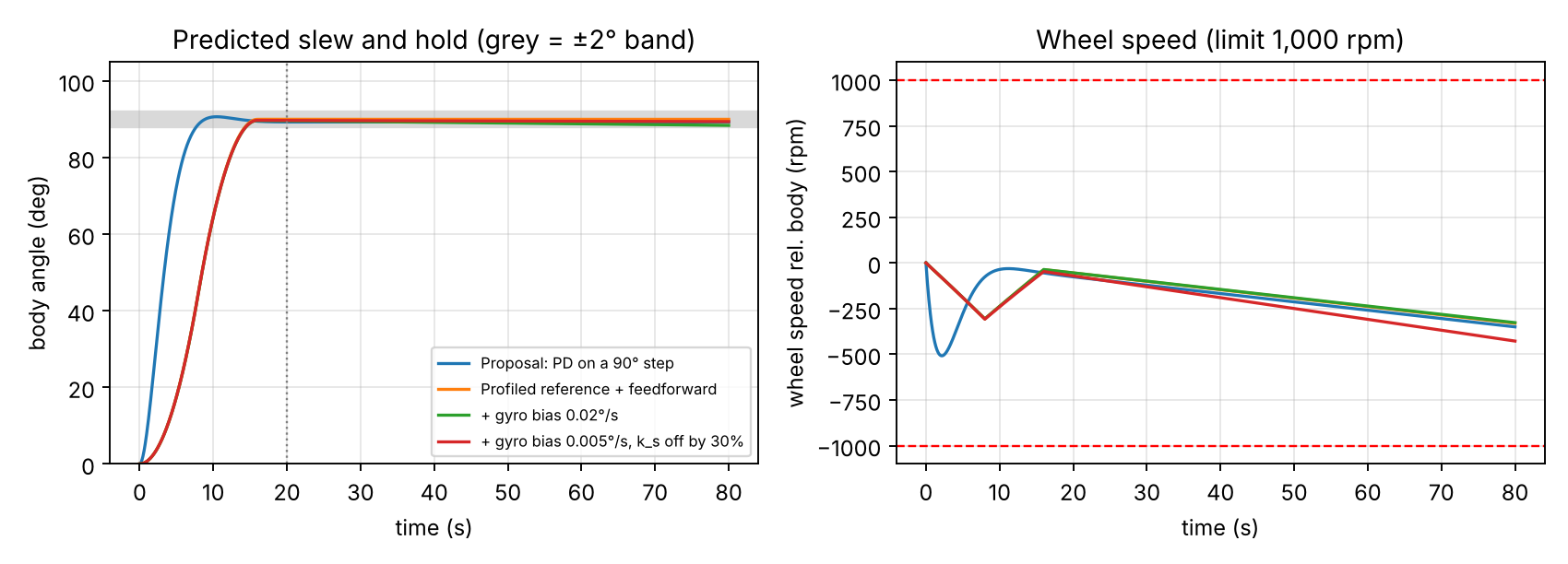
Slew and hold response from the Gate 1 model. Test data from T-09 and T-10 is added to this plot as it comes in.
Design decisions
| Date | Decision | Why |
|---|---|---|
| Nov 2026 | Brass flywheel, gimbal BLDC with FOC | Smooth low-speed torque, enough inertia in a small disk |
| Nov 2026 | Add line-twist feedforward | Error budget showed 2.7° against ±2°; feedforward brings it to 1.1° |
| Nov 2026 | Inner wheel-speed loop | PWM steps too coarse for fine torque |
| Nov 2026 | Camera as truth sensor only | The controller never grades its own work |
Not uploaded yet.