CubeSat Space Readiness Test Chamber
- Role
- ADCS & Simulation Lead · Test & Safety Lead
- Dates
- Sep 2026 – May 2027
- Status
- In progress
- Tools
- MATLAB, Simulink, Stateflow, FreeFlyer
- Project
- Capstone
Abstract
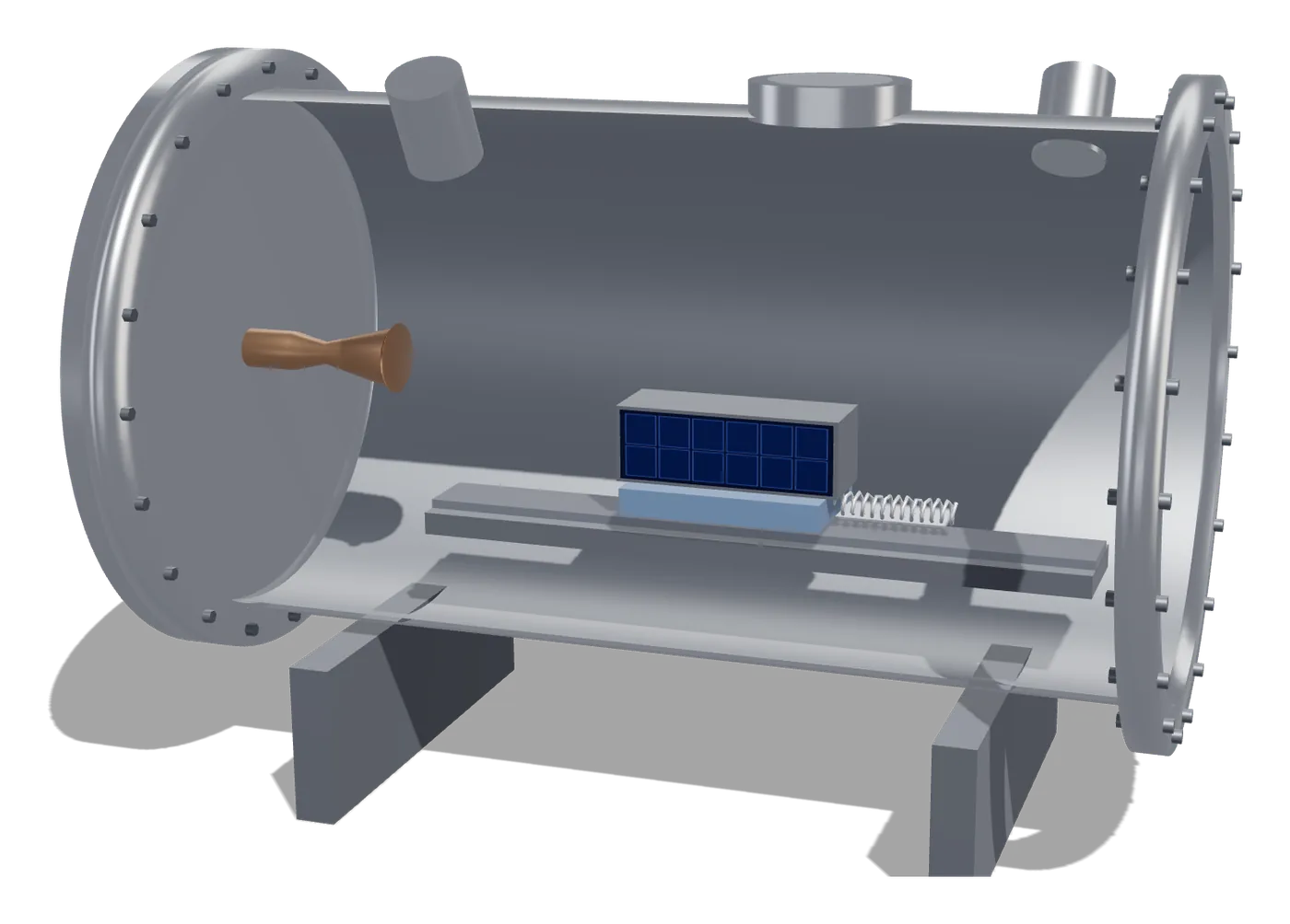
A vacuum chamber that puts 1U–3U CubeSat models in a simulated 200–300 km orbit using a heated gas nozzle and a magnetically levitated carriage. I lead the redesign of the satellite's attitude-control simulation and run test and safety.
An audit of the inherited model found five gaps. The largest: at 250 km, air drag twists the satellite 13× harder than the gravity-gradient torque, and the model never carried that term at all. Chamber drag also runs 240–4,200× higher than orbit, so the simulation carries bench results out to orbit through drag coefficients rather than assuming they transfer.
The control design is hybrid: the lab's micro-thrusters hold roll with 15× authority over the disturbance, and magnetorquers take pitch and yaw.
Take it apart
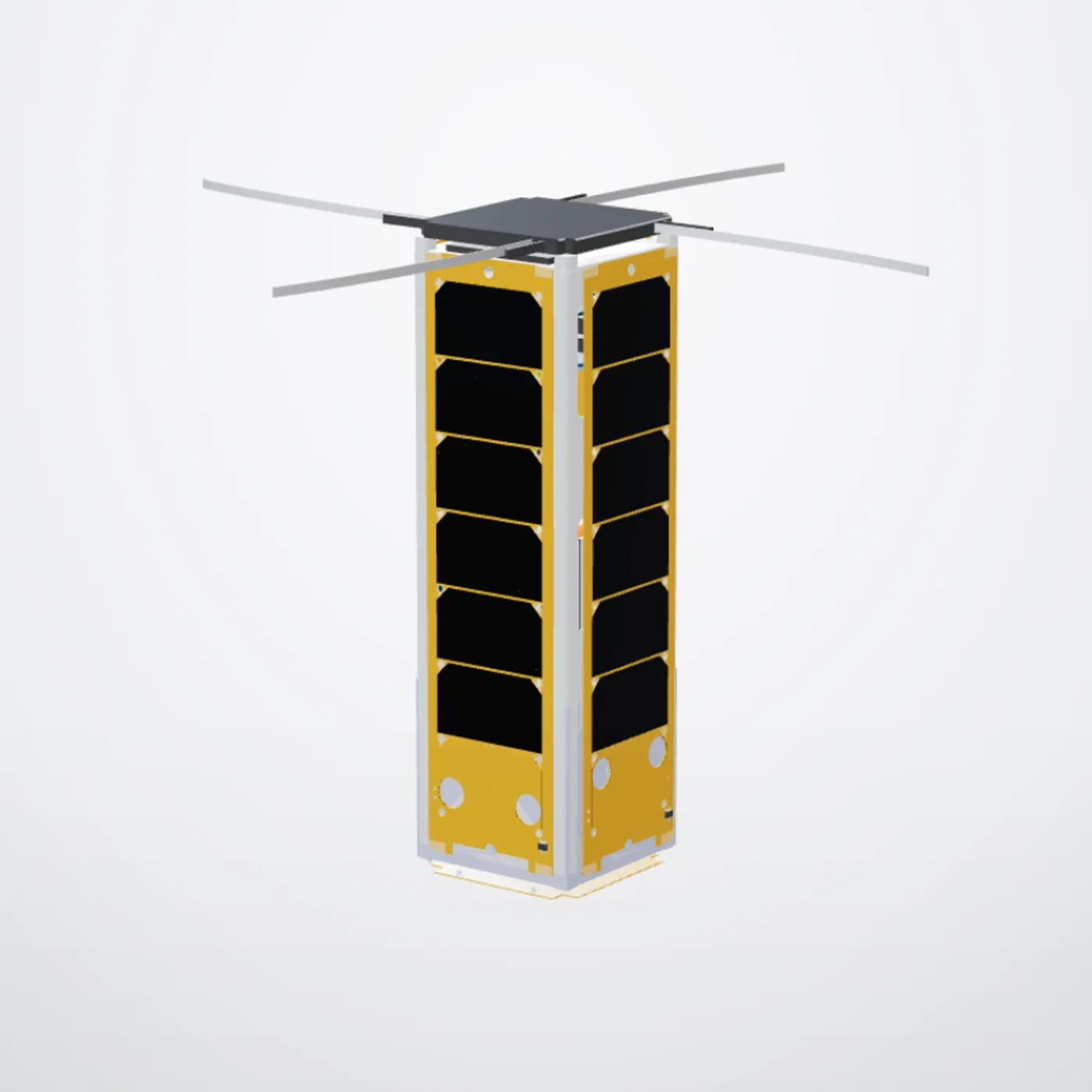
The attitude-control module, and the spacecraft it has to turn: a 3U chassis, four body-mounted solar panels that set the inertia, the power it draws from and the UHF link its commands arrive on. Scroll to take it apart.
- The assemblyWhat it is, put together.
- Taken apartKeep scrolling. Every part comes off along its own axis, the way it would on the bench.
- What each part doesClick any label, or any part, to see its name and why it is there.
GW-Sat, GWU MAE capstone (built on the prior team's design). My role: ADCS simulation and attitude control.
Files
4 folders · 4 files · 1 open in the browser, nothing downloads. 3 files are not uploaded yet.
Analysis
Capstone / 02_Analysis| Type | File | Rev | Date | Status | Open |
|---|---|---|---|---|---|
| ADCS_First_Order_Analysis.pdfDisturbance torques, control authority, chamber scaling | — | — | Planned |
CAD
Capstone / 03_CAD| Type | File | Rev | Date | Status | Open |
|---|---|---|---|---|---|
| MD | Every part in the exploded model, and what it is to the attitude control | A | Nov 2026 | Current |
Simulation
Capstone / 04_Simulation| Type | File | Rev | Date | Status | Open |
|---|---|---|---|---|---|
| MD | ADCS_Simulink_Model.mdMEKF, PID modes, thruster allocation | — | — | Planned |
Report
Capstone / 09_Report| Type | File | Rev | Date | Status | Open |
|---|---|---|---|---|---|
| ADCS_Report.pdfMy ADCS write-up | — | — | Planned |
| Item | Part | Spec | What it is for |
|---|---|---|---|
| 01 | ADCS Module | — | Attitude determination and control — the subsystem I work on. The simulation, the control modes, and splitting the job between the lab's micro-thrusters and the magnetorquers. Everything below is either a body it has to turn, a load on it, or a service it needs. |
| 02 | 3U Chassis | 703-00292-E0 | The structural skeleton every module bolts into. It is also the body the attitude control actually turns: where mass sits in it is what sets the inertia in the equations of motion. |
| 03 | Solar Panel — front | 710-00771-B | Body-mounted cells on the long face. The panels are fixed, so pointing and power are the same problem — attitude decides how much the satellite collects. |
| 04 | Solar Panel — side | 710-00772-B | One of three side panels. Their placement is what sets the inertia about each axis, so it decides how much torque a slew needs. |
| — | Solar Panel — side | 710-00772-B | One of three side panels. Their placement is what sets the inertia about each axis, so it decides how much torque a slew needs. |
| — | Solar Panel — side | 710-00772-B | One of three side panels. Their placement is what sets the inertia about each axis, so it decides how much torque a slew needs. |
| 05 | Solar Panel — end | 710-00837-B | Closes the end face and carries the antenna mount. On the short face it is the smallest contributor to the inertia the control has to swing. |
| 06 | Power Board (EPS) | 711-00338-D | Takes the panels' output, charges the batteries and regulates the buses. It is what the thrusters and magnetorquers draw from, so it bounds how hard and how often attitude control can act. |
| 07 | Battery Module | 710-01552-F | Stores the energy the satellite runs on in eclipse. Two modules sit low in the stack to keep the centre of mass down. |
| — | Battery Module | 710-01552-F | Stores the energy the satellite runs on in eclipse. Two modules sit low in the stack to keep the centre of mass down. |
| 08 | Motherboard | 710-00484-D | The backplane the avionics stack plugs into, carrying power and data between modules. |
| — | Motherboard — second board | 710-01362-E | The second board in the stack, extending the bus to the remaining modules. |
| 09 | UHF Radio | — | EnduroSat UHF transceiver — the link to the ground station. Attitude commands come up this way and the attitude telemetry goes down it. |
| 10 | UHF Radio — second unit | — | EnduroSat UHF transceiver — the link to the ground station. Attitude commands come up this way and the attitude telemetry goes down it. |
| — | PCB | — | Placeholder board standing in for avionics still being specified. |
Item numbers match the numbered callouts on the exploded view. A dash means the part is on the model but carries no callout.
Not uploaded yet.